- Global Supply | Worldwide Delivery

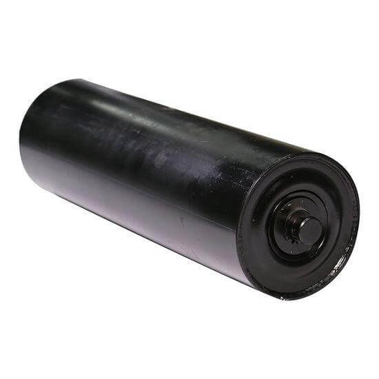
Carrying Rollers are rotating support components positioned beneath the loaded side of a belt conveyor. They help support the conveyor belt and conveyed material while also maintaining the intended belt profile. In addition, carrying rollers can be configured according to roller diameter, tube thickness, shaft dimensions, bearing arrangement, seals, overall length, trough angle, and operating environment. Therefore, selecting the appropriate carrying roller configuration is important for smooth conveyor operation, reliable belt support, and consistent material handling.
Share Your Conveyor Roller Requirements With Us and Get the Best Price, Tailored to Your Needs. Our Team Will Respond Quickly With a Competitive Quote.
Ten key specifications presented as engineering cards rather than a conventional table. Values shown are typical selection ranges; the final specification is determined by the conveyor duty and approved drawing.
76.1–165.1 mm
Selected according to load, belt speed and bearing arrangement.
3.0–7.0 mm
Final thickness depends on roller load, diameter and material.
20–60 mm
Verified for bending, shear, bearing fit and mounting.
As per conveyor drawing
Matched to belt width, trough arrangement and idler frame.
20–60 mm
Matched to shaft diameter and selected bearing series.
1 bearing at each end
Sealed bearing arrangement selected for duty and environment.
0.75–1.50 m typical
Closer spacing may be required for heavier loads or special zones.
20° / 30° / 35° / 45°
Selected according to belt, material and idler-frame design.
ERW steel / SS / HDPE
Material selected according to load, corrosion, hygiene and application.
Up to application requirement
Final speed depends on roller diameter, bearing rating, balance and conveyor duty.
A simple material-load calculator for preliminary carrying-idler selection.
Enter your conveyor values and calculate the material load supported between carrying-idler stations.
| Material Load per Metre | |
| Material Mass Between Stations | |
| Material Force at One Station |
Stop and isolate the conveyor. Check bearing seizure, contamination, shaft alignment, seal interference and mounting pressure. Replace the roller if free rotation cannot be restored.
First, check actual roller reaction, bearing rating, shaft fit, sealing, contamination and operating speed.
Next, inspect the bearing, seal, tube runout, shaft alignment and balance. Grinding or rumbling normally indicates that the roller requires inspection or replacement.
Inspect for seized rollers, sharp edges, damaged tube surfaces and excessive runout. Remove defective rollers before they damage the belt further.
In addition, review idler spacing, material lump size, loading impact, tube diameter, and wall thickness.
Meanwhile, check idler-frame alignment, roller position, seized rollers and belt condition. Correct the mechanical alignment rather than using a damaged roller as a tracking solution.
Inspect seals, shaft surface, bearing housing and washdown conditions. Select sealing for the actual environment and replace contaminated components.
Finally, check tube concentricity, shaft straightness, bearing seating, balance, and mounting.
A carrying roller supports the loaded belt on the carrying side of a belt conveyor. A typical troughed arrangement uses a centre roller with two wing rollers.